LSM SERIES STIRLING ENGINES, a work in progress.
Stirling Engine Operational Principle:
Stirling cycle engines operate on a closed cycle in which a quantity of gas (called the working fluid), is alternatively heated and cooled. Mechanical power is generated by the heated gas expanding against a piston. It is then moved to a cool space and contracts before being returned through the heater to repeat the cycle. Gas control is entirely by volume changes, not by valves. The traditional working fluid is air, but nitrogen is sometimes used because itâs less corrosive. For high performance, helium and hydrogen are better because their thermal conductivity is much higher- and hydrogen is also less viscous.
For high specific outputs (power for size), the working fluid is pressurised- sometimes to more than 100bar.
Stirling engines are built in three main mechanical layouts: alpha, beta and gamma. Alphas use two single acting cylinders connected via a heater, regenerator and cooler, with the pistons around 90 degrees out of phase to shuttle the working fluid back and forth. Four-cylinder alphas (like the Whispergen) have every cylinder leading the following one by 90 degrees, with the top of each connected to the underneath of the next. They have only one main seal per cylinder which minimises seal friction.
Betas have a single acting piston and a double acting displacer, in the same cylinder (concentric), also at around 90 degrees crank phasing.
Gammas use a double acting displacer in one cylinder and a single acting piston in a second cylinder, also at around 90 degrees phase.
Additionally, there are free piston Stirling engines which use the beta layout. Their piston and displacer motions are controlled by springs, gas pressure, inertia, and electromagnetism (they use linear alternators to extract power), not by a crank.
A hybrid form called Ringboms use crank-controlled pistons with their displacer moved by weight, inertia and gas pressure.
Early History:
Engines with Stirling-like features were built from around 1800 (including by airplane pioneer Sir George Cayley in 1807), but their invention is generally credited to the Rev. Robert Stirling, after whom they are named. Stirling, a Scottish Presbyterian minister, developed the first practical valveless closed cycle engine and patented the regenerative heat exchanger (a key feature) in 1816.
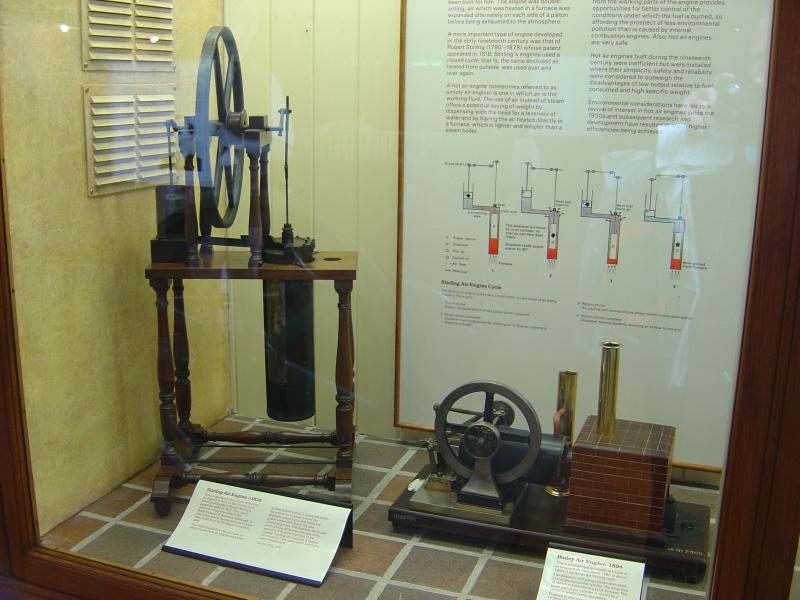 Robert Stirlingâs gamma hot air engine from 1816 -1823, Kensington Science Museum (original is in the Edinburgh Museum). A full-size replica of this engine is displayed in the Stirling Engine collection at the Mahan Heritage Centre, Geraldine New Zealand.
It is run on request.
External Combustion:
Heat is applied externally to Stirling cycle engines (like for steam engines), rather than internally (as for the diesel or petrol engine and most gas turbines). They can therefore use the combustion of any solid, liquid, or gaseous fuel- or a high temperature source such as solar, nuclear, or geothermal.
High Efficiency:
In 1840, French scientist Sadi Carnot described the second law of thermodynamics, which sets a limit (the Carnot cycle) for thermodynamic efficiency that cannot be exceeded by heat engines no matter how perfectly they are designed or constructed. It is a function only of the maximum and minimum temperatures, the formula being (Th â Tc)/Th where T is temperature in degrees Kelvin, h is the hot end, c is the cold end. Engines using the Carnot cycle directly without employing heat exchangers have not yet proven to be practicable. Rudolf Diesel mistakenly thought that he could achieve this and caused much embarrassment to himself and his licensees by claims to this effect made in his original patent. Stirling engines (and their open cycle Ericsson cousins) are the only heat engines that are theoretically capable of Carnot efficiency. They do this indirectly by using heat exchangers to store heat energy remaining in the working fluid after expansion and returning it after the cooling stage. Stirling engines operating on a cycle reasonably close to their theoretical cycle can be built.
19th Century Popularity:
During the 19th century, Stirling cycle air engines (often called hot air engines) were relatively common, especially for water pumping, but also for sewing machines, dentist drills, and domestic fans. Unlike steam engines, they did not require boilers, but low power and high cost limited their uses. An 8â Ericsson Stirling engine (1870âs to 1930âs), weighs 350kgm, develops 200watts (1/4hp)- and could cost more than an average yearâs income back then. Production of Stirling cycle air engines tapered off in the early 20th century as electricity reticulation spread and inexpensive internal combustion engines became generally available.
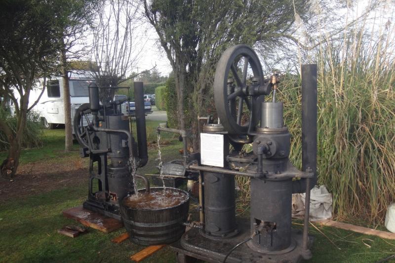 Circa 1900 8 inch Ericsson (beta) and 6 inch Hayward Tyler (alpha) hot air pumping engines, Orari, 2019
20th Century Revivals:
Driven by the multi-fuel options of the Stirling cycle and its high potential efficiency, there were many attempts at reviving the Stirling engine during the 20th century. Some were aimed at mainstream applications such as cars, but Stirling engines were also developed for submarines, solar electricity generation, artificial hearts, and combined heat and power (CHP) units- in which small Stirling engines generate electricity for household use (typically gas powered) with waste heat being applied to water heating (Whispergens for example).
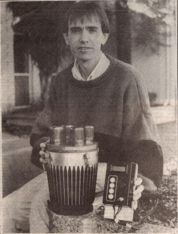 Dr Don Clucas with an early Whispergen, 1993
Theory Versus Practice:
the reality after 200 years of striving by countless engineers and huge expenditure (more than NZ$100million for Whispertech I believe), is that Stirling engines have yet to find any long-term mainstream market except for toys, for refrigeration (the thermodynamically efficient Stirling cycle, used in reverse for cooling, is particularly useful when very low temperatures are required) and for submarines (combustion can be at very high pressure- and theyâre quieter than nukes). Combined heat and power units (CHPs) are currently not economic for general use, even with "green" subsidies. Nor have Stirling engine powered products yet secured any significant place in the off-grid market- though some are advertised. Various solar Stirling energy park projects have foundered as the cost of photovoltaics has come down (Infinia for example).
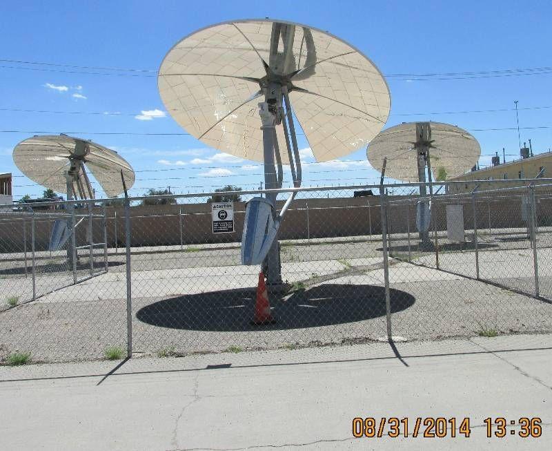 Infinia 3.5Kw free piston solar Stirling engines at a US demonstration solar farm (these units are in âsleepâ mode with their mirrors facing downwards). There is an Infinia mirror unit and an extra engine in the Mahan collection.
Why have Stirling engines not (yet?) found practical applications? The essential problem is that their theoretical efficiency has so far proven to be unattainable without exceeding a price that makes the engines impracticable. Even very expensive designs using hydrogen or helium working fluid pressurised to more than 50 atmospheres are typically less than 25% efficient and have low specific output (power for size). They compare unfavourably with compact petrol engines that approach 30% efficiency, diesels with more than 40%, solid-state photovoltaics- and solid-state refrigerators for thermal imaging applications. Free piston Stirling engines may still buck this trend; they are simple in concept but difficult to design and very demanding of materials and manufacturing tolerances.
Unfinished business:
The Whispergen saga (1987 to 2013) in which I had a small part, raised quite a few questions of the type that are interesting to me and that I became able to pursue from about 2008. Whispertech began in my workshop in 1988 when Don Clucas, who had worked for me while at school and for a few years full time, returned to start his engineering PhD developing a Stirling engine based combined heat and power unit. After Southpower (an electricity provider) came in as a sponsor, development moved to Christchurch, and my direct involvement ceased (by the early 1990âs kite traction- my real job- was really taking off). The Whispergen design soon settled on a 4 cylinder âalphaâ layout- in the main because of its perfect balance and heat transfer scale effects which favour small cylinder sizes. Don had also invented the wobble-yoke crank system, which gave the embryonic company what the backers felt was essential IP. Early commitment to this layout was a necessary business decision at the time but did shut out consideration of other options. Since 2008, I have been indulging myself (and having a lot of fun) by trying various other mechanical layouts in a series of one-off engines: LSM 11 to LSM 21 (a Ringbom, 2023). I donât have expectations of commercial opportunities or of finding something that the world will find useful, itâs for the challenges and to satisfy my curiosity.
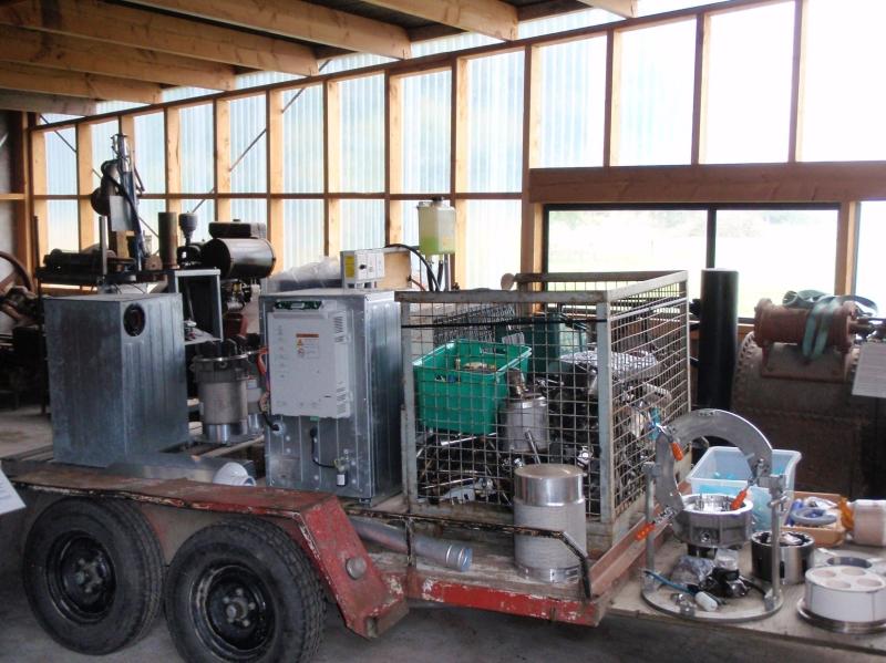 Some Whispergen leftovers came back to Ashburton when Whispertech closed in 2011.
LSM series specifications and build approach:
From the late 1960âs through to 2008, I had made (or attempted to make) around 10 Stirling engines. Most were radical- like a single piston with transfer ports that I hoped would operate on a Stirling cycle and another with a rotating piston that alternatively exposed hot and cold surfaces. None of these ran most didnât even achieve Jude 2 (see Stirling engine power scale below). The others were more conventional.
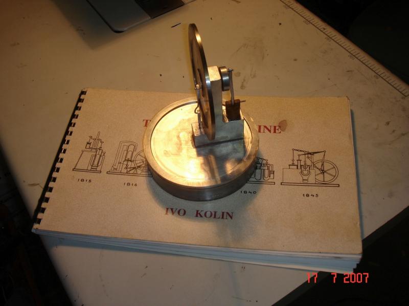 Own make coffee cup gamma Stirling engine 2007
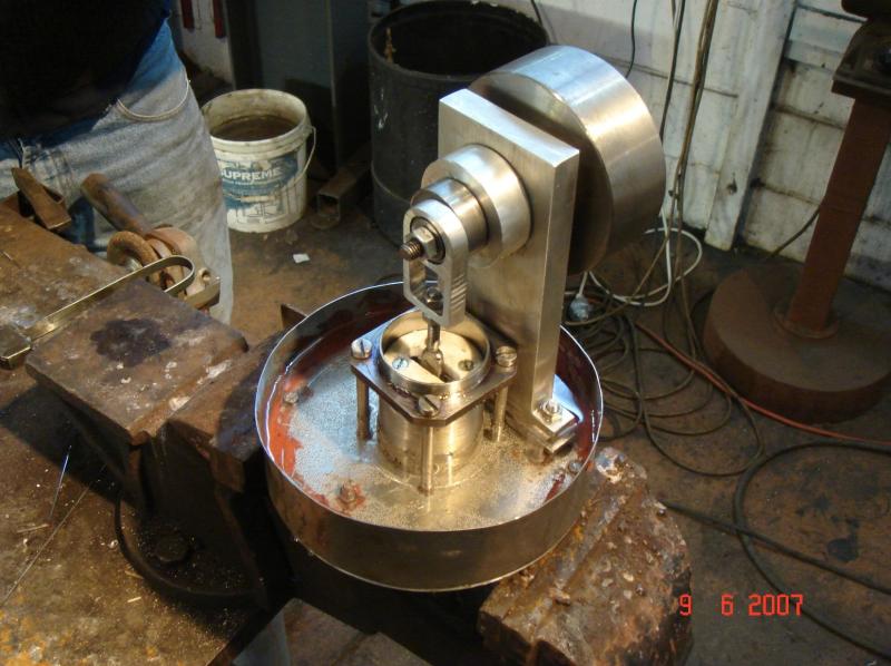 Beta Stirling engine with magnetically coupled displacer, 2007
From 2008, I have made a series of larger engines.
LSMâs 11, 12, 13, 14, 15, 16, 18, and 21(Ringbom) are betas, 17 and 19 are alphas. 20 has a combined piston/displacer that changes volume- I call these adiabatics.
To make comparisons easier, all of them have swept volumes of around 2.5 litres, use air as the working fluid and are unpressurised. I chose this larger size mainly so that in unpressurised form, these engines would have enough power to be somewhat useful and so that I wouldnât fool myself with the heat transfer scale effect that makes small Stirling engines much more likely to be successful then larger ones. Larger size engines are also easier to make with ageing eyesight! LSM 14.1 is in a launch- which does 5knots with 3 people aboard. LSM 12.2 is in a mobility scooter, has a 5-speed gearbox and a max speed of around 15km/hr. LSM 15.4 drives a rocking chair as a museum display.
Unpressurized Stirling cycle engines (generally called hot air engines) are not renowned for power output. Many struggle to even overcome their own friction.
They've had very little influence on the world, except for a brief period of popularity in the late 19th/early 20th century when not requiring a boiler certificate was enough advantage to offset the fundamental handicap of low specific output (by size and cost) and as models (benefiting from the area/volume scale effect).
Accordingly: As the standard power measurement systems by which engines are rated do not show hot air engines in an advantageous way, I believe they should have their own special power scale (with apologies to Watt and a nod to Beaufort). Itâs called the Jude Scale- after Saint Jude the apostle- and patron saint of lost causes.
Jude 1: No discernible preference for rotational direction.
Jude 2: Clear rotational direction preference but not self-sustaining.
Jude 3: Almost self-sustaining; tantalisingly close to.
Jude 4: Occasionally self-sustaining but sometimes stops spontaneously.
Jude 5: Mostly self-sustaining- almost never stops spontaneously.
Jude 6: Easily self-sustaining- with excess enough to run its cooling fan or pump.
Jude 7: Some power: Could spin the "Lotto" wheel (for small numbers).
Jude 8: Useful power; like from half an unfit person on an exercise machine.
Jude 9: Really useful power; enough for a mobility scooter (but not uphill).
Jude 10: Power commensurate with cost and complexity (Never achieved yet).
I donât build these engines as an exercise in model engineering- the engineering is a means to an end, not an end in itself- my excuse for rough and ready construction!
They mainly use conventional cast iron piston rings- because these are much more resistant to occasional temperature spikes and have a lot less friction than Teflon based dry seals. Surprisingly, oil residue build-up has not been a problem so far- though CI rings do pretty much preclude the use of mesh regenerators (they get clogged). LSM 14.1 (which has an annular gap type regenerator) has run for 100âs of hours in an 8m replica 19th century Great Lakes gentlemanâs launch and does not yet require de-carbonising.
LSM 14.1 displacer still clean after 100âs of running hours:
Not pressurising the working fluid is partly to make the engines more visually accessible but also because âatmosphericsâ are a style that has been neglected since the 19th century except for toy engines- most would say for very good reason considering their low specific power! So called âsnifterâ one-way valves can be used to boost pressure in the working space a little, but I have met very few air engines ever (especially antique ones) that donât run better with the snifter off, because the pumping losses from the snifter generally exceed the gains from higher density working fluid. Sealing has to be exceptionally good for snifters to be useful.
I also confess to two other foibles: using found materials and âdesigning as I buildâ- sketches but no drawings.
Flywheels, water tanks, steel pipe, stainless steel, disc brakes (for rings), bolts, and ârecycledâ bearings are generally all âfoundâ materials. This is not because of necessity or âgreenâ credentials but because I get satisfaction from this (yes, I have Scottish ancestry). I havenât yet found a free source of argon gas for TIG welding nor for drill bits, milling cutters and tungsten inserted tips.
The âno drawingsâ approach is a sort of intellectual challenge- like chess I suppose. Can I think out the entire design in advance and hold it in my head well enough not to have any bits inconveniently trying to occupy the same space when itâs time to put everything together? The order in which parts are made can make this a lot easier, and I do record some dimensions- and have failures, which I donât much talk about.
A handicap is my lack of facility with CAD (computer assisted design), and CFD (computational fluid dynamics)- which is rather embarrassing, seeing as in 1968 I was possibly one of the first NZ engineers to have the opportunity to play with an embryonic program in this field- âIBM Stressâ (on an IBM 360). My two engineer sons have only contempt for these inadequacies.
A 1980âs reverse Polish notation Hewlett Packard calculator still gets plenty of use. and I do have a Stirling engine modelling program into which I can plug numbers. I havenât yet had useful predictions from this - an experience that parallels Dr Donâs (ex Whispertech CEO, now a Uni lecturer) who also has a rather low opinion of their usefulness.
Since the 19th century, new materials (stainless steel especially), improved fabrication techniques (like TIG welding), inexpensive rolling element bearings and better understanding of thermodynamics have informed significant performance gains for unpressurised hot air engines. Specific output (power/swept volume) of the LSM series is around twice 19th century averages. They are also much more compact (a particular focus of mine) and are MUCH lighter. LSM 14.1 weighs less than 100kgm, has the same swept volume and twice the power of the more than 300kg 8â Ericsson pumping engine in the photo above.
If there is insufficient heat transfer area, revs and hence power is limited. If there is more than enough, gas flow losses rise, and extra dead space reduces volume changes- which limit output. Alpha layouts generally achieve higher compression ratios, so are less sensitive to this than betas. Around 1,200 sq.cm of cold end heat transfer area and 1000 sq.cm for the hot end have so far proven suitable for this range of engines.
There is also an optimal area for the gas flow passages. Too large has a dead volume cost, too small causes pumping losses- to which low power unpressurised engines are sensitive. But smaller cross sections provide better heat transfer by turbulent flow- a complex balance. For LSM series engines, between 11sq.cm and 15sq.cm works well- though they often end up with a larger cross section than desirable for mechanical reasons. This is because, for beta engines, it is difficult to keep the gap between the displacer and the hot end cylinder to under 3mm (which is a 20 sq.cm flow path for a 200mm bore) entirely by sliding elements that are more than 500mm distant, as is necessary for non-contact displacers. Itâs easy enough to do in the workshop when the engine is cold, but with the hot end at more than 500 degrees, temperature asymmetries in the burner and even wind effects (asymmetric heating), dreaded scraping noises are never far away, especially after a few hundred hours running. Nothing spoils a pleasant cruise on the lake as much as crunching sounds when the displacer scrapes against the hot end cylinder-and the accompanying drop in boat speed. All the beta LSMs (11, 12, 13, 14, 15, 16, 18 and 21) have different displacer guide systems. All of them are satisfactory. 12.2, 14.1 and 16.4 are the most compact. As an aside here, the displacers in Ericssonâs 19th century beta hot air engines have small diameter rods that are deliberately flexible so that the displacer can self-centralise by flow effects alone. LSMs generally use skirted displacers so I have never been quite brave enough to try this.
When developing these engines, I use simple tests to determine whether any change is an improvement. For friction and sealing, a swing on the flywheel tells a lot; if itâs easy to turn and bounces 3 or 4 times on compression, then friction is low, and sealing is good. Another is how soon an engine will start after lighting the burner and how long it will run for after turning it off. How far the heat can be turned down without causing the engine to stop is a useful indicator also. For checking ring sealing, if a squirt of oil on the rings causes a noticeable but short-lived increase in revs then sealing is poor. Perhaps the best test of an unpressurised air engine is how far open a tap to the working space can be without causing the engine to stop. Quite a few of the LSM series will run with a 6mm diameter vent to atmosphere. This is a severe test for an air engine as it attenuates the working fluid as well as applying a pumping load.
Unfortunately, I havenât found dynamometer testing to be as useful for comparative testing as I initially expected because for all LSM engines the main determinants of output have turned out to be sealing, friction and heater efficacy. Reducing friction, improving sealing or providing more heat often results in more gains than changes to phase or piston/displacer relative stroke. This sometimes makes it difficult to come to definitive conclusions about mechanical arrangements. Because unpressurised air engines are so sensitive to friction and sealing, they very often run better and better with running time.
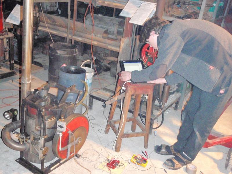 Dynamometer set up on LSM 12-2, Andreas Fischbacher, 2009
 LSM 11, 2008:
11.1 An early theme was to make an engine that could power a boat using driftwood, and later, by burning books- my brother-in-law disposes of tonnes of them in his connection with Ashburtonâs yearly Bookarama. There was also a cheeky idea to burn religious tracts- which can arrive at your door free of charge, given even the slightest encouragement (free energy!).
11.1, a beta, was therefore made for solid fuel, though I soon found out that higher class literature has too much clay in the paper for clean burning, while Mills and Boons are excellent (and conveniently sized). It has tube heat exchangers (stainless steel for the hot end, copper for the cold) which necessarily require that the displacer has seals. This causes some extra friction, and these rings inevitably run hotter than the pistonâs rings, which can be a problem. Whether a result of this extra friction or other causes (pumping losses through the tubes or inadequate heating?), 11âs output has probably never exceeded 200watts (11.3) - though this is still a higher specific output than the 19th century hot air engines I was comparing with at that time. 11.3 has a form of straight-line linkage for displacer control which works well but is more complex than the displacer guides used for some later LSM engines. The mesh regenerator was removed when it clogged with carbon from burnt lubricating oil that had made its way to the hot end. There are ways to arrange such regenerators so that they can be cleaned by periodically burning them out without dismantling the engine, but Iâd not thought ahead sufficiently to design 11 with this feature- and burning out has to be done quite often so is not practical for some engine applications. 11.1 was developed through 11.2 to 11.3 (2009) with improved linkages, displacers and pistons. Jude 8.
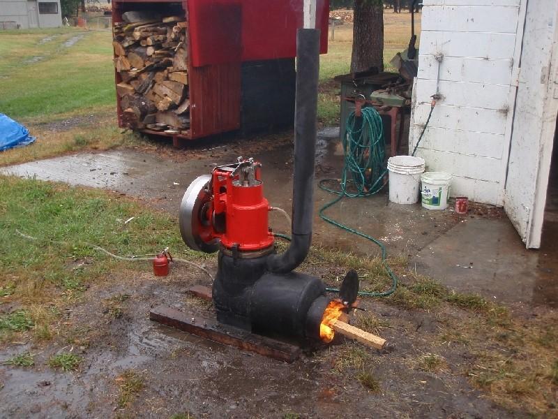 LSM 11.3 beta, running on wood, Ashburton, 2009.
LSM 12:
12.1 was an attempt at an Ericsson open cycle engine. My intent in trying an open cycle approach was to eliminate the need for a cold end heat exchanger and its attendant cooling system, saving weight and size. This isnât possible for pressurised engines of course but seemed like a useful feature for unpressurised LSMs.
It was a miserable failure because the complicated valving system I had contrived (sliding sleeves around the cylinder) did not seal adequately. Valves have historically been the weak point for open cycle air engines- because they operate near the hot end where lubrication is unavailable, so have a short life. This failure was particularly abject because the valving didnât even work when cold. 12-1 never showed a preference for rotational direction (Jude 1).
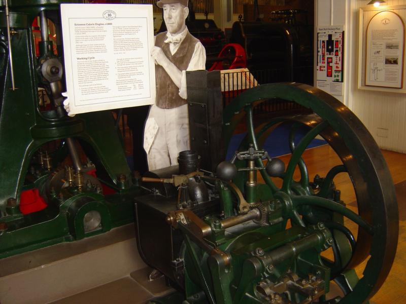 Ericssonâs 1869 Caloric engine at Kensington- Iâve failed twice with Ericsson cycle engines
12.1 was then re-built as a closed Stirling cycle engine (12.2) in which form it ran well. This was installed in Piwakawaka (8m launch) until superseded by the more powerful LSM 14.1, then further improved (to 12.3) with work on the displacer and piston and a better heater. It was then fitted first in a motorcycle and lately a mobility scooter. Jude 9.
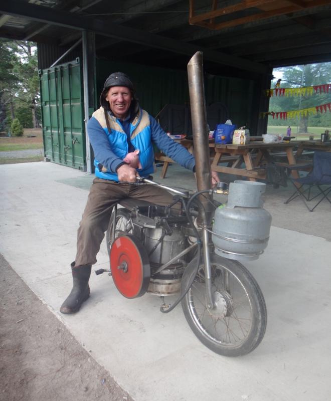 LSM 12.3 in a motorcycle, 2015- with CVT transmission
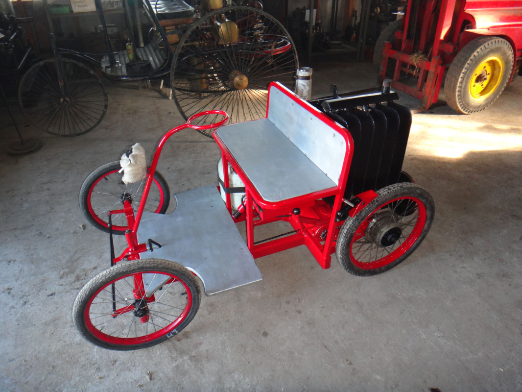 LSM 12.3 in a mobility scooter, 2023- 5 speed (so it does go up hill- slowly) and reverse.
LSM 13:
13.1 is a fully balanced beta by virtue of double geared cranks. In 2012 I was overconcerned with balance, not understanding that other parameters (specific output, efficiency, reliability, complexity, cost) matter much more. There are very few applications where balance is crucial and where it is, engines can be mounted to minimise vibrations anyway. For example, 12.3 in the above mobility scooter is supported on a balanced spring-loaded linkage. I think this mistaken focus on balance was also an enduring impediment for Whispergens- their 4 cylinder fully balanced alphas are complex. A single cylinder approach (such as the Philips 102C) could have been lighter and much less expensive.
13.1 has an extreme bore/stroke ratio (320mm bore, 32mm stroke). The theory behind this being that main seal frictional losses for reciprocating engines is in an inverse relationship with bore- the larger the bore the less friction losses for the same swept volume. Unfortunately, the leakage path also increases with bore and for 13.1 I have been unable to get good enough sealing without using silicone rubber ring expanders. These add unwelcome friction. Recently it was tried with a carbon/graphite packing backed with a square section Si rubber expander in place of the 2 conventional CI piston rings. This packing sealed no better than Si rubber expanded CI rings and had about the same friction- but was prone to leaking until warmed up. It did have the advantage of being oil-less.
Heat transfer (hot and cold ends) is inadequate in 13.1.
Its geared flywheel is excellent (except that itâs noisy).
13.1 is by far the smallest LSM series (2.5 litre swept volume) engine.
It explores some useful ideas, but in retrospect should have been 400mm bore by 20mm stroke (to get adequate heat transfer area) and used a diaphragm rather than piston rings for sealing. Jude 5.
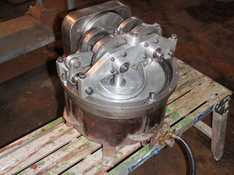 LSM 13.1 with fan and shroud, 2011
LSM 14:
14-1 is probably my most successful engine judged by output, reliability and usefulness- but not the most interesting. Itâs a conventional beta with a non-contact displacer, annular heat transfer surfaces and an annular gap regenerator (which reduces conduction between hot and cold ends, but does it really do much regenerating?). The side flywheel and rocker layout is compact and provides scope for changing the piston and displacer strokes and their relative phase without altering the crank (which is a simple cantilever). Except for a change from a ring burner to a double venturi burner, 14-1 has not been developed in any significant way, since it was first built and has become the reference standard for the series. Jude 9.
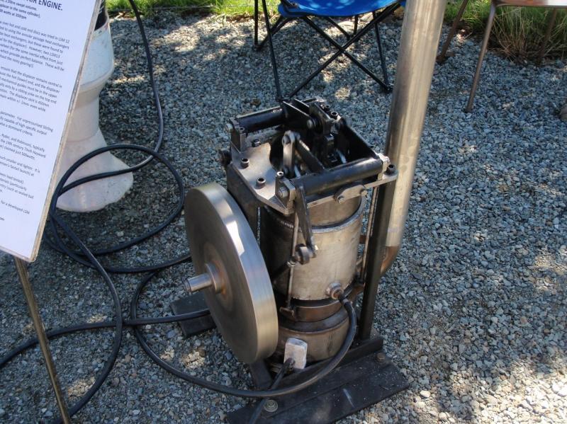 LSM 14.1 first start-up in 2012 before installation in Piwakawaka (8m launch).
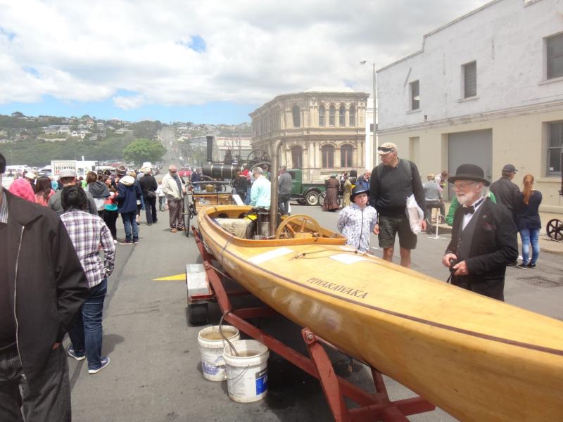 LSM 14.1 in Piwakawaka at Oamaru 2014
 LSM 15:
15.1 was an air-cooled beta with a cast aluminium cooler, seals on the displacer (slow learner, see 11.1) and a stop motion crank (a first attack on the âtransfer problemâ, see 16.4 and 18.1 below). It barely ran. By 2020 it had been through 3 more iterations and had water cooling, a contactless displacer, a star linkage transfer) and is an excellent engine- now powering a rocking chair as a wry comment on the general usefulness of Stirling engines. To match the engine speed to the rockerâs natural frequency, 15.4 is fitted with a Watts type governor that operates by progressively opening a valve in the working space to atmosphere. Jude 8 (and could be Jude 9 if its steel piston wasnât inclined to seize when pushed hard).
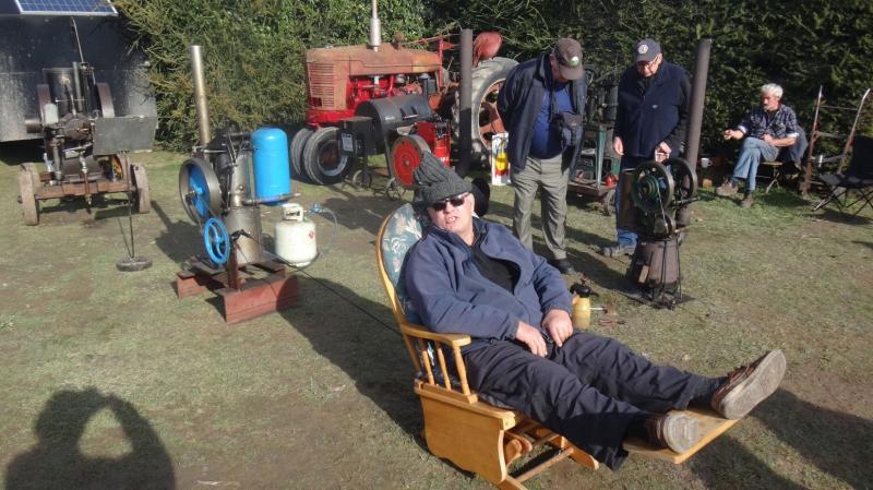 LSM 15.4 showing what Stirling engines are capable of, 2021
LSM 16:
16.1 had a double skirted displacer and a water-cooled piston but was changed to a quite different layout before it was completed. Instead of a piston and displacer it was tried with a combined piston/displacer that can change length as it reciprocates. I call this the adiabatic layout as the power taken by repeatedly compressing the piston/displacerâs internal volume is largely recovered adiabatically. By 16-3 it was running well, very promising. A disadvantage of this layout is that in its simplest form, the piston/displacerâs internal seal is subject to higher temperature than if running against an externally cooled surface. Advantages are that itâs simpler than alphas, betas or gammas, is more compact, excludes dust, and is easy to pressurise. As piston ring seal lubrication was inadequate on 16-3, a new engine, LSM 20 was built to further test the adiabatic concept and 16 was rebuilt again (eventually 16-4) to try another idea (see below). 16-4 is Jude 8.
LSM 17:
17.1, an alpha, was an open Ericsson cycle engine- now usually called the Brayton or gas turbine cycle- This was my second attempt at an open cycle air engine (see 12.1) and was also a failure- this time because I tried what I thought could be better layout than Ericssons. It wasnât- or, more likely, pumping losses were too high. Itâs beyond embarrassing that I havenât been able to get an open cycle engine to run- even with all the advantages of materials, methods and understanding developed in the 175 years since Ericsson WAS successful.
17.1 was then re- built as a conventional alpha Stirling engine, 17.2 (covid lockdowns provided lots of uninterrupted workshop time) with a Ross yoke. It was then further developed with a different Ross yoke variant (17.3) and runs very well. Jude 8- might even get Jude 9 with more heat.
John Ericsson did also eventually give up on open cycles engines and adopted the Stirling cycle- funny that.
LSM 18:
18.1 is an attack on what, in my view, is one of the main failings of Stirling engines that use conventional (including rhombic) crank controlled linkages.
To explain this, I shall first describe how heat transfer in Stirling engines works. The theoretical cycle is for the working fluid to emerge from the regenerator at its maximum (or minimum) temperature and then have heat added (or removed) as expansion (or compression) occurs to maintain the working fluid at constant temperature during these parts of the cycle (isothermal expansion and compression is an essential characteristic of the Stirling cycle). In practice, working fluid passes from the regenerator into a heater (or cooler) and then into the expansion (or compression) space where it expands (or contracts) with a significant temperature drop (or rise).
In both alpha and beta engines, more than 50% of the expansion (which is what generates the power) happens after the working fluid has begun to pass back through the heater, regenerator and cooler into the cold space. Gamma layouts are at least as bad in this respect- they generate power via a piston which is in the cold space and responds to general variations in the working fluid pressure (the gamma layout is however very suitable for low temperature difference engines, and for toys and models that have only to overcome their own friction).
The best way to understand this less-than-optimal working fluid transfer is to look at the physical models I use that are with the collection at the Mahan Heritage Centre- yes, yes, I should get a nice dynamic Solid Works depiction of this organised someday so you can see it on-line. Iâm not sure how much effect this transfer effect has on efficiency, though it must be negative because the working fluid is being cooled even as itâs expanding against the piston to do useful work. It certainly costs specific output (power per swept volume). In the 19th century there were various attempts at addressing this problem using cams- but none of these achieved enduring success (because of friction I suspect). Model low temperature gamma Stirling engines are sometimes made with slotted linkages so that displacer motion is paused while the power piston completes its expansion and compression strokes. It has the added advantage of running either way. I made one like this in the late 1980s (see photo above), but this solution is not scalable.
Working fluid transfer is entirely a function of mechanical arrangement.
Free piston engines could perhaps be arranged to have better transfer but donât ever seem to be. This is most likely because of the limitations imposed by how their displacer and piston motions are controlled (various complex harmonics).
18.1 (beta) uses a modified Whitworth quick return motion which causes the displacer to stay with the piston for almost its complete power stroke before returning rapidly to transfer working fluid to the cold space at the beginning of the pistonâs compression stroke. It is a substantial solution to the transfer problem- at some cost in friction, additional inertial and element loads, and a question as to whether the displacerâs rapid return affects the cooling phase.
 LSM 18.1 quick return crank mechanism, 2020
LSM 16.3 was then completely re-built (still in the covid lockdown) with links and pivots that accomplish nearly the same result but without cams or rolling surfaces- so, lower loads and less friction. This linkage was largely inspired by the geometry of Ericssonâs Caloric engine patent, so maybe my dive into open cycle engines wasnât entirely wasted. Unfortunately, that niggling question about the effects of displacer quick return motion on cooling came to the fore. LSM 16.4 ran well but still not up with 12 or 14. It was then re-built with a simple crank (LSM 16.5) and is now in the range of 12 and 14. LSM 18.1 was then rebuilt with yet a further (and this time successful) attempt at getting better working fluid transfer. See LSM 18.2 below.
 LSM 16-4 with quick return displacer linkage.
LSM 19:
19.1 (still under construction at May 2025) is an attempt at addressing redundant heating and cooling which I see as the other main failing of current Stirling engines.
There is inherent inefficiency in passing the working fluid back through the heater (cooler) after expansion (compression). Theoretically the working fluid is already at max (min) temp as it re-enters the heater (cooler) but in practice there is a significant temperature drop (rise) during expansion (compression). An effect of this is that the working fluid then enters the regenerator at higher (lower) temperature than it would otherwise be, which requires the regenerator to be larger than necessary. This imposes extra gas flow losses and more dead space. There are also unnecessary extra gas flow losses in the heat exchangers themselves.
LSM 19.1, a type of alpha, is to use a mechanical slide valve to route the working fluid directly from the expansion and compression spaces to the regenerator, bypassing unnecessary extra passes through the heater and cooler. This could be done with pressure operated automatic (non-return) valves, but Iâve settled on mechanical operation for now to reduce pressure losses and to be able to fiddle with timing. Although the hot end valve must function at up to 500 degrees, it can be non-contact as even 90% flow control should be enough to show substantial improvement. For years I have been trying to work such valving into a beta but never found a practical arrangement- and had concerns about excessive dead space, which betas are more sensitive to. For years Iâve also been trying to figure a way to accomplish this goal by using swirl- keeping the working fluid rotating around the piston and displacer axis so as to give it preference for a port that short circuits the heater (cooler)- but havenât been that confident of my attempts to calculate the effects (and Iâm not able to peer in there to see what is actually happening). Lately (2025) Iâve been considering whether there is a role for Tesla valves in this. Tesla valves are a no-moving-parts device that restrict fluid flow in one direction while allowing free flow in the other. Heat exchangers could be formed as Tesla valves to make flow substantially one- way- or they could be applied to the regenerator.
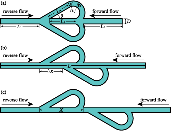
In the longer term, swirl and/or Tesla valves may be the best solution- but first I need to find out whether the expected benefits materialise.
LSM 20:
20.1 is a development of the adiabatic concept (see LSM 16) 16.3, had a displacer that changed volume in place of the conventional piston and displacer beta layout. It showed promise but had inherent problems which could not be practically solved except by starting over.
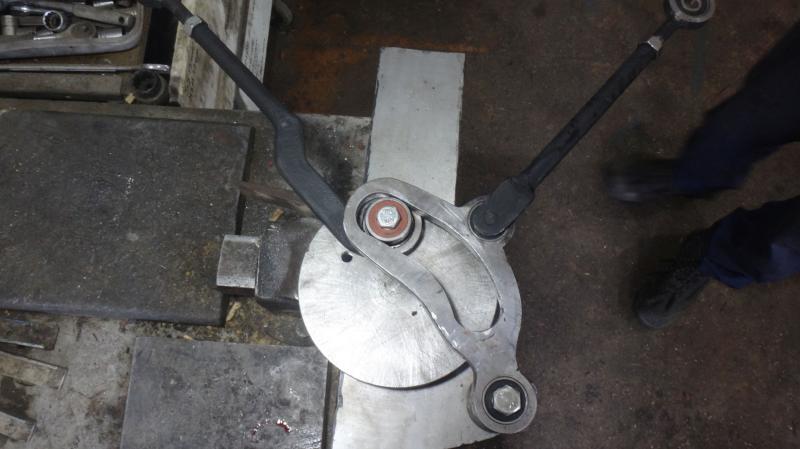
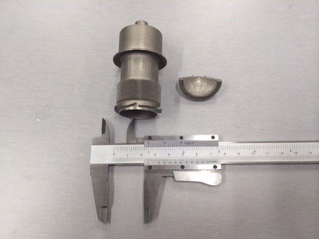
These were addressed in 20.1 by making the displacerâs upper surface conical so as to distribute oil evenly to the rings, shifting the rings to the upper displacer where they run them cooler and by changing the water jackets to function by thermosiphon rather than pump. Phase angle was also increased from 58degrees to 78 degrees to improve working fluid transfer. 20.1 runs well- for a short time- then succumbs to an issue that also plagued 16.3 (adiabatic). This is that, to minimise the displacerâs weight, the cylindrical section on which the rings run is machined quite thin- 4mm. As the engine heats up, this goes out of round and the rings lose sealing. Let it cool and itâs away again. Jude 4- because it wonât (yet?) run continuously.
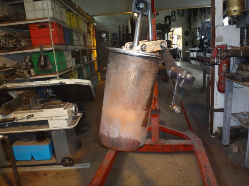
 Checking for displacer distortion in LSM 20. When heated, the top part of the displacer goes out of round by as much as 4mm- causing the rings that run in this section to lose contact (ring plate on the welding table to the left).
LSM 21:
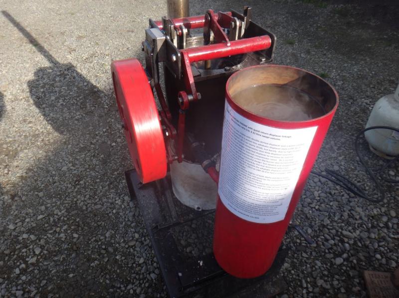
Iâve previously shied away from delving into free piston engines because gaining a useful understanding looks to be several lifetimes work but have more recently (2023) built a Ringbom to extend the Stirling engine display at the Mahan Heritage centre. Ringboms, invented by Ossian Ringbom in 1905, are halfway towards the free piston concept, having a crank controlled piston but with the displacer controlled solely by inertial, weight and pressure forces. 21.1 is an alpha layout and uses neodymium magnets to limit displacer travel and stop banging- which is otherwise a feature of Ringboms (they are colloquially called bang bang engines). It runs great, is a favourite display engine (along with the 1816 Stirling replica and the 15.4 rocking chair) for museum visitors. 21.1 graphically demonstrates a peculiar characteristic of Ringboms- that they generally have two operating modes. The first (when the heat is set low) is when the displacer operates on a very short stroke- some 30mm or so for this engine. With more heat the displacer abruptly starts using its full available range- 130mm. With full heat, the magnetsâ repulsion is overwhelmed and 21.1 reverts to bang bang form. Jude 7- itâs built for demonstration not as a serious attempt at specific output.
What have I learnt, where to from here?
13.1 is a dog in its current dimensions- itâs noisy and barely runs- but its inherent compactness makes it worth having a second look at. Having perfect balance may not be the holy grail many Stirling engine designers believe but itâs not to be sneezed at either. The double crank system also allows the piston to be a guide for the displacer. Sealing could be fixed with a diaphragm instead of rings (makes it oil-less also, opening the way for a mesh regenerator rather than an, always inadequate, annular gap type). Increasing the bore to 400mm and decreasing the stroke to 20mm increases the heat transfer areas to what I have found to be optimal for unpressurised 2.5 litre swept volume air engines. Could the diaphragm be a metal bellows or would crank loads then be too high (friction)?
14.1. In retrospect, I was very lucky with 14.1 in 2012 to get so many parameters so close to optimal for an unpressurised beta air engine of this swept volume. Solely from the view that itâs unlikely all of these are exactly right, some improvement should be available by tinkering with the piston/displacer stroke ratio, phase angle and heat transfer areas-. A lighter and better baffled displacer would certainly be an improvement. 12.3 has been incrementally improved until it at least equals 14.1âs power. Itâs similarly compact though a bit shorter and wider and has lately been more reliable (14.1 experienced a displacer buckle in 2022 when pushed hard, since repaired). I wonder whether 12.3âs regenerator- a long annular path as for 14.1 but with the addition of SS gauze attached to the cylinder wall- is a worthwhile improvement?
15.4 is better than it should be. Through its various iterations, 15 went from being a dog to a star- and I donât have a full understanding as to why. Thereâs something worth investigating in this- is it the star linkage, is the displacer guide system better (supported by a longish piston), is it the lower bore/stroke ratio (less than all other LSMs)? Itâs not as compact as most of the other LSMs but compactness is not a primary concern for every application. 15.4 has a steel piston/steel bore which tends to pick-up when put it under load at max revs so cannot currently be tested for maximum power.
16.4 is not as good as it should be. Is this because of poor sealing, inadequate heating or something to do with the displacerâs quick return motion? This could be checked by making an alternative connecting rod to bi-pass the current QR linkage. If the problem is the QR motion (which shortens the working fluidâs time going through the cooling heat exchanger), some other way will have to be found to cause the displacer to track with the piston for a lot more than 50% of the expansion stroke.
18.2 at October 2025 is excellent- showing real promise, with what seems to be much better working fluid transfer- which Iâve been chasing for years. Transfer in18.2 is just a first try at this particular linkage and will undoubtedly respond further to optimisation. The approach of looking at five WF parameters, not just the one (18.1 and previously) has paid off. Nor would I make an identical 18.2 if making next version- itsâs not very compact, could probably be better served with different displacer control (like 16.5 for example) and maybe a skirted displacer (at some heat transfer cost but useful if compactness is a criteria).
19.1 (eliminating redundant flows through the heater and cooler) will be very interesting. If thereâs a discernible improvement in output relative to other LSMs then controlling transfer by swirl and/or Tesla valves will be worth investigating. Iâm particularly interested in how much it can potentially decrease the size of the regenerator (saving flow losses). Any decrease in regenerator dead space will also offset some if not all the extra dead space required for alternate flow paths.
20.1 (adiabatic) has real promise but a solution has to be found for cylinder distortion that doesnât increase the displacer weight (needs to decrease). The cause appears to be asymmetric expansion of the lower displacer section pulling the top cylinder section out of round- in which case radial bracing could be a fix. A radical cure would be to replace the ring/cylinder sealing with a stack of stainless steel belleville washers welded into a metal bellows (available off the shelf in multiple sizes). This would also allow higher internal temperature (overheating was a problem for the rings in 16-3 and possibly is for 20.1). I donât expect hysteresis losses in the bellows would be a killer but would the mechanical loads attending the bellowsâ âspringâ increase friction by too much?
Except for 19, which Iâm still working on, all the LSM (Lynn Stirling Motor) engines are runners. They are displayed at the Mahan Heritage Centre in Geraldine New Zealand along with an extensive collection of historic Stirling engines.
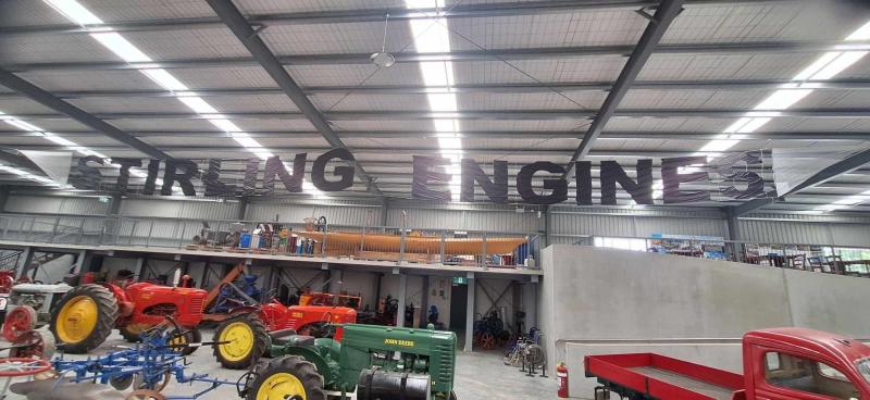 Stirling engine display on the mezzanine floor at the Mahan Heritage centre, 2024 photo
Are Stirling Engines really a lost cause?
The record so far is pretty dismal: I was seduced by a Philips 102C when I was 15 and have never really recovered. Fortunately, Iâve had a lot of enjoyment and satisfaction from my playing around- and havenât done myself much harm except maybe that the time could have been better spent (but would even more time playing with kites have improved my utility score?). Unfortunately, I infected Don Clucas (yes, I know, a mixed metaphor), which led to the ultimately unsuccessful Whispergen saga. I do apologise to New Zealand taxpayers, electricity consumers and especially to Don for this.
Itâs now more than 200 years since Robert Stirlingâs 1816 epiphany and thereâs very little thatâs currently useful to show for the many broken dreams and huge expenditure of time and money. Low temperature refrigeration is about the only bright spot, with making stealthier submarines maybe also having some impact (I regard submarine applications as positive- not being able to detect nuclear armed subs is what has kept the world from nuclear Armageddon since the 1950s). I sincerely hope that anyone who now picks up the ball and runs with it does so purely for curiosity and the satisfaction of occasionally getting something new to work, not from thoughts of saving the planet, becoming a famous inventor or having a successful business.
There are some recent developments that do offer new directions for Stirling engines that may (just may) prove useful.
3D metal printing is one- better heat exchangers and regenerators than were possible even 10 years ago.
 Superior 3D printed Stirling engine hot end heat exchanger- impossible prior to this new technology
CFD (computational fluid dynamics; digital modelling of gas flow and heat transfer) is another. Perhaps this field has now developed to the point where predictions approximate the real world well enough to eliminate the need for most physical prototyping. Thermo-acoustic and free piston engines could be the big winners.
An obvious next step is pressurisation.
The LSM series have all been made to around 2.5litre swept volume and to run unpressurised. This was to provide comparison while keeping the mechanism easily accessible for changes. Of course, output per swept volume and overall size is very low, but Iâve also seen this as a useful challenge â highlighting the need for low friction, good sealing and relative compactness. Sure, optimisation within this restriction is not always scalable to pressurised engines but has led to some useful insights.
With only one avenue left to explore with the LSM series (19.1, with valved working fluid transfer passages- not yet completed) the next step is to try pressurisation and improve the derisory (and widely derided) specific output so far achieved.
Up to around 3 bar, I expect pressurisation to increase output about proportionately- that is by 3 times. Above this, thereâll be some slippage I expect- largely because heat transfer areas may not then be large enough to provide the necessary energy transfer A factor which helps the initial boost is that WF pressure in an unpressurised engine is less than 1 bar because internal pressure equalises to 1 bar over the cycle not to when the piston is at maximum swept volume. Three bar pressurisation therefore provides nearer to a four imes increase in WF pressure.
Snifter valves, commonly used on unpressurised antique hot air engines, theoretically correct this deficit by letting air in when internal pressure is below atmospheric and stopping its escape when above. But I have found that pumping losses due to even minor piston leakage generally offset any gains made. For example, I have yet to meet a Heinrici which performs better with the snifter engaged than when it shut off.
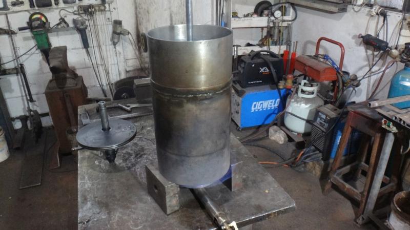
Three bar pressurisation could possibly cause the hot end heat exchanger to blow out on most LSM engines at high temperature as itâs usually only 2mm or less wall thickness, but an increase to 3mm or 4mm will not much effect performance except for slowing start-up a bit. Unless an engine is being built from scratch, I suggest trying first without increasing the hot end heat exchanger wall thickness as it may hold, and if it doesnât, the firebox and surround will limit consequences. If strengthening proves necessary, it will also likely involve changing the heated end cap to convex rather than concave (and the displacer end cap to match).
The best way to provide pressurisation on a side flywheel LSM engine will be to extend the crank rocker shafts by 50mm or so at the flywheel side, shift the bearings to these extensions and provide them with seals. To minimise friction loses, these extensions could be 25mm diameter solid shaft rather than the 45mm or so diameter of existing rocker tubes. To enable assembly, the crank rocker arms would then be fitted to these rocker shaft extensions with splines. After this, a bolt down cap could be made to seal the engine. I suggest this approach because it does not cost compactness and seal losses will likely be less than a single rotating seal on the crankshaft because each of the rockers rotates through less than 45 degrees- equivalent to 180 degrees of total rotation as compared to 360 degrees for a crankshaft seal.
With 1kw output or more, LSM engines become practical for some real-world application like wood fired pumps and generators- and for boats (providing enough extra power for weed chopping, a problem for Piwakawaka in some waters.
AI is the big one.
AIs will inevitably take over the evaluation and optimisation of possible designs- but will they also supplant human creativity by proposing completely new designs? I wouldnât bet that they wonât.
Peter Lynn, Ashburton, New Zealand, November â25