Peter Lynn ARCHIVE
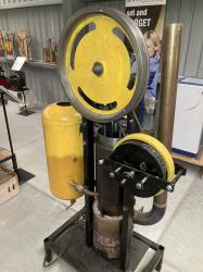
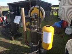
Ringbom type, 185mm bore, 100mm stroke piston, 2.7 litre swept volume
In 1905 Ossian Ringbom of Helsinki Finland applied to patent a Stirling engine that uses pressure differences rather than a crank or linkage to move the displacer. For Stirling engines, internal pressure fluctuates around the average pressure (which is atmospheric pressure for unpressurised engines). Ringbom’s insight was that this could be used to move the displacer, eliminating a crank and linkage.
Unpressurised Ringboms use a displacer actuating rod with substantial diameter that is open to the atmosphere at one end. When internal pressure is above atmospheric, the displacer moves away from the heated end, and the working fluid passes to the heated space. When internal pressure is below atmospheric, the displacer moves towards the heated end and the working fluid passes to the cold space.
There is no evidence that Ringbom ever built such an engine, but others did.
Two problems immediately manifested.
The first is that motion of this type is what’s called a coupled pair- the displacer motion influences the piston motion and vice versa. This manifests as cyclical variations in displacer stroke length and position. Often there will be two distinct stable modes- long and short displacer strokes- and sometimes a combination. At that time mathematical analysis was not up to modelling this (it’s still difficult because there are many variables). This caused the Ringbom concept to languish until relatively recently.
The other (connected) problem was to stop the displacer from crashing into the piston or cylinder end. For model engines, ‘O’ rings are adequate bump stops. For larger engines, gas cushions or springs can be used. Unfortunately, gas cushions rob power, and springs are only effective for a specific speed and load. For this reason, Ringboms tend to be single speed engines, as are Professor Beale’s free piston engines (which don’t use crank control for the piston either, taking power out by linear alternator).
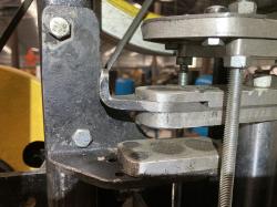
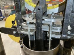
This engine uses opposing magnets to stop the displacer hitting either the piston or the cylinder end. Permanent magnet fields are what’s called ‘conservative’- energy that’s expended in pushing opposing magnets together is completely recovered when they again move apart. Their resistive force builds up rapidly over just a few millimetres of travel to act as a stroke limiter that’s almost completely independent of speed and load.
The key Ringbom parameter is the ratio of piston area to displacer rod area. 21.1’s piston is 185mm diameter and its displacer rod is 35mm diameter. It was first tried at 50mm, expecting that this was likely too large- replacing with a smaller one being easier than having to go larger.
There’s a belt driven eddy current brake to prevent over revving, (which can cause the displacer to overwhelm the magnetic end stops), but it still takes delicate adjustment of heat and load to get the displacer to settle into the preferred long stroke mode.
PETER LYNN, ASHBURTON, NEW ZEALAND, to MAY 2025.